Using this thread to share screenshots, etc as we build, and fill in the gaps between Kickstarter updates.
2 Likes
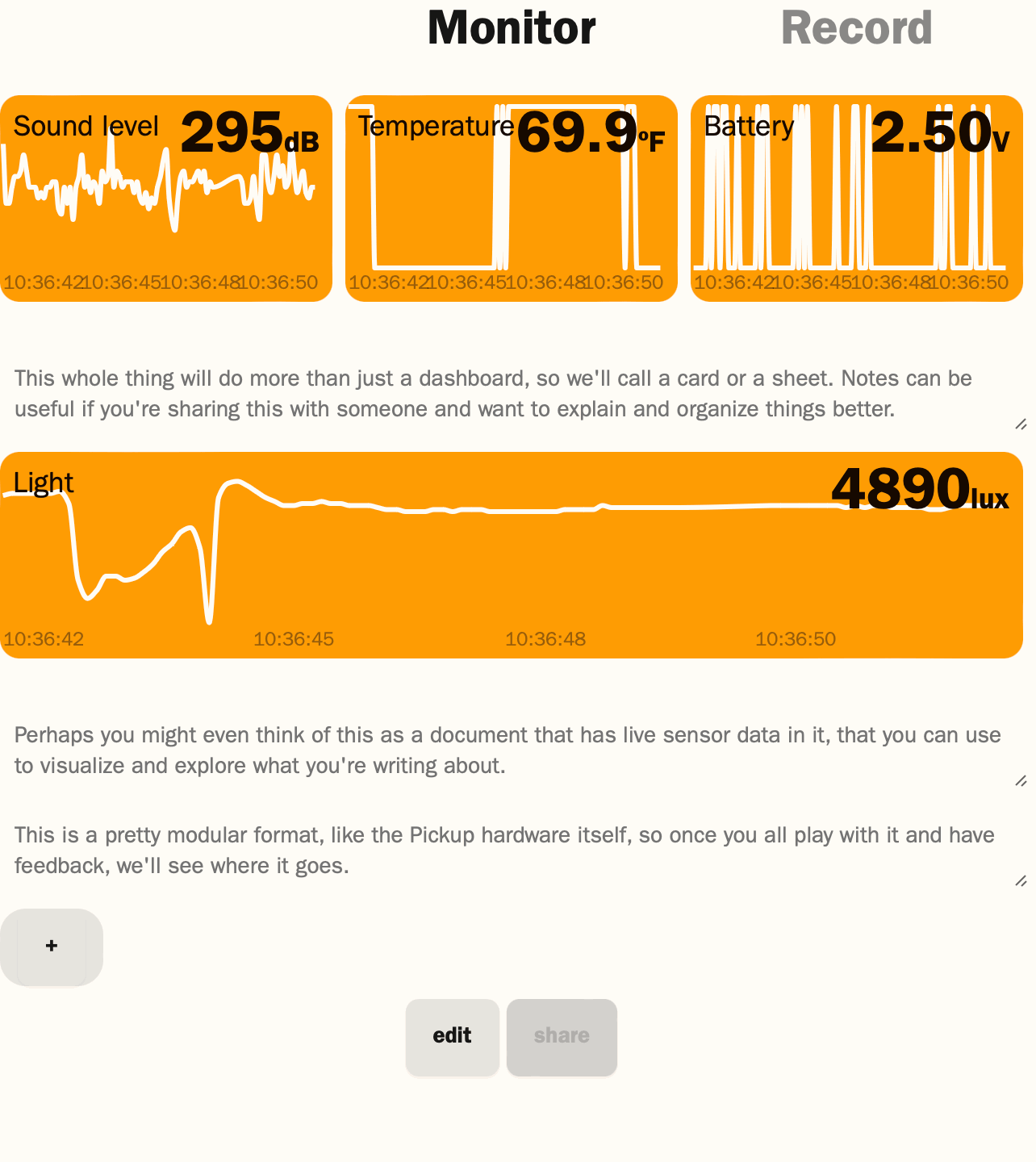
Got the case design files off to the molder and ordered the molds, so that gave me some time to finally get back to software. Here’s a dashboard reading sensors from one of our first boards (data is uncalibrated) over MQTT. Most of the time it won’t update this fast—that’d drain the batteries—but it’s handy for testing.
1 Like
I’ve been working on what we call “slow mode”. This is the normal mode when running on batteries. Pickup will sample the configured sensors, go to sleep, sample again as needed, and then connect to WiFi and transmit the data. Both the sensor sampling and the WiFi rates are individually configurable.
Here’s the basic hardware setup, this is a Nordic PPK2 power profiler:
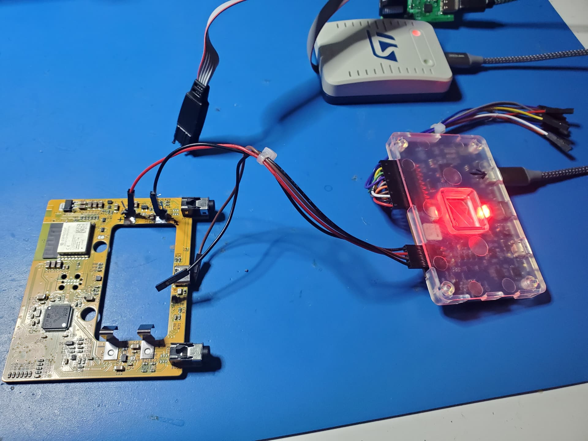
And here’s what the complete cycle looks like. This is with a 10 second sensor rate and a 30 second WiFi rate (we call it telemetry rate):
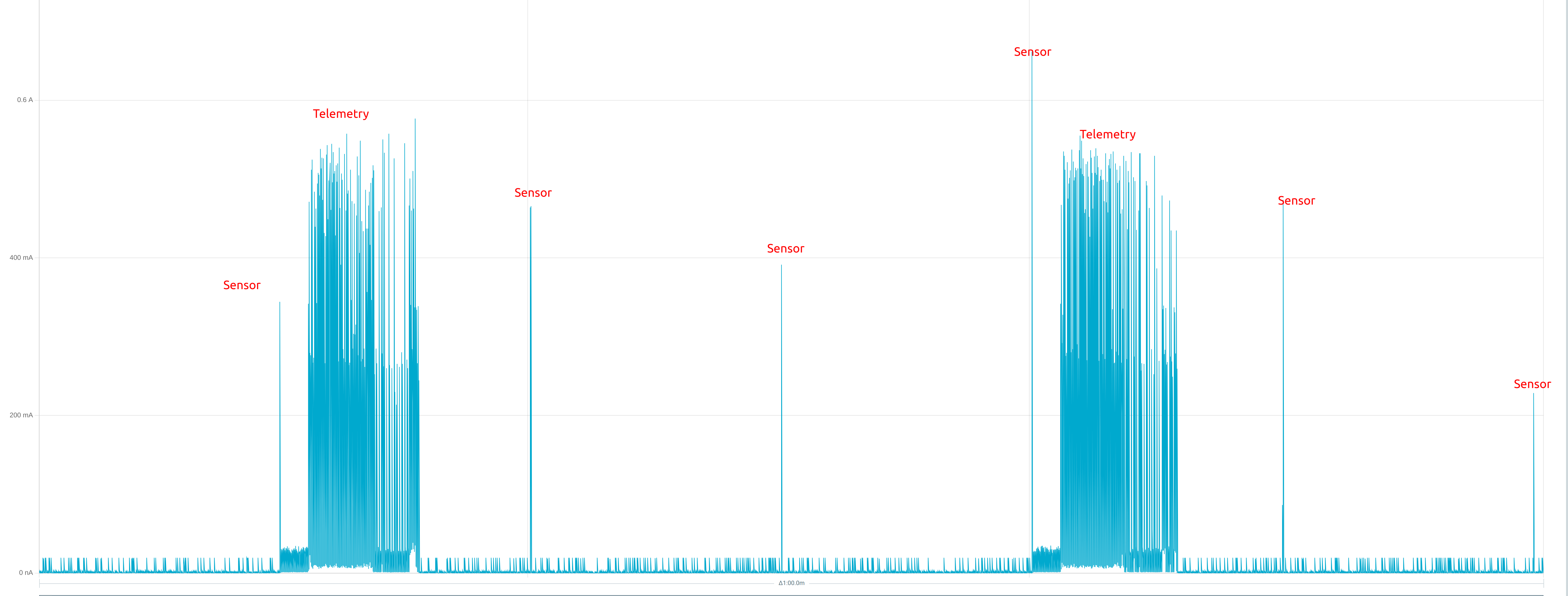
You can see the sleep mode power at the very bottom, then narrow spikes when it wakes up for sensors, and then the larger chunks for the WiFi.
Finally, the actual sleep mode power, since it is hard to see how low it is with the sensor and WiFi power:
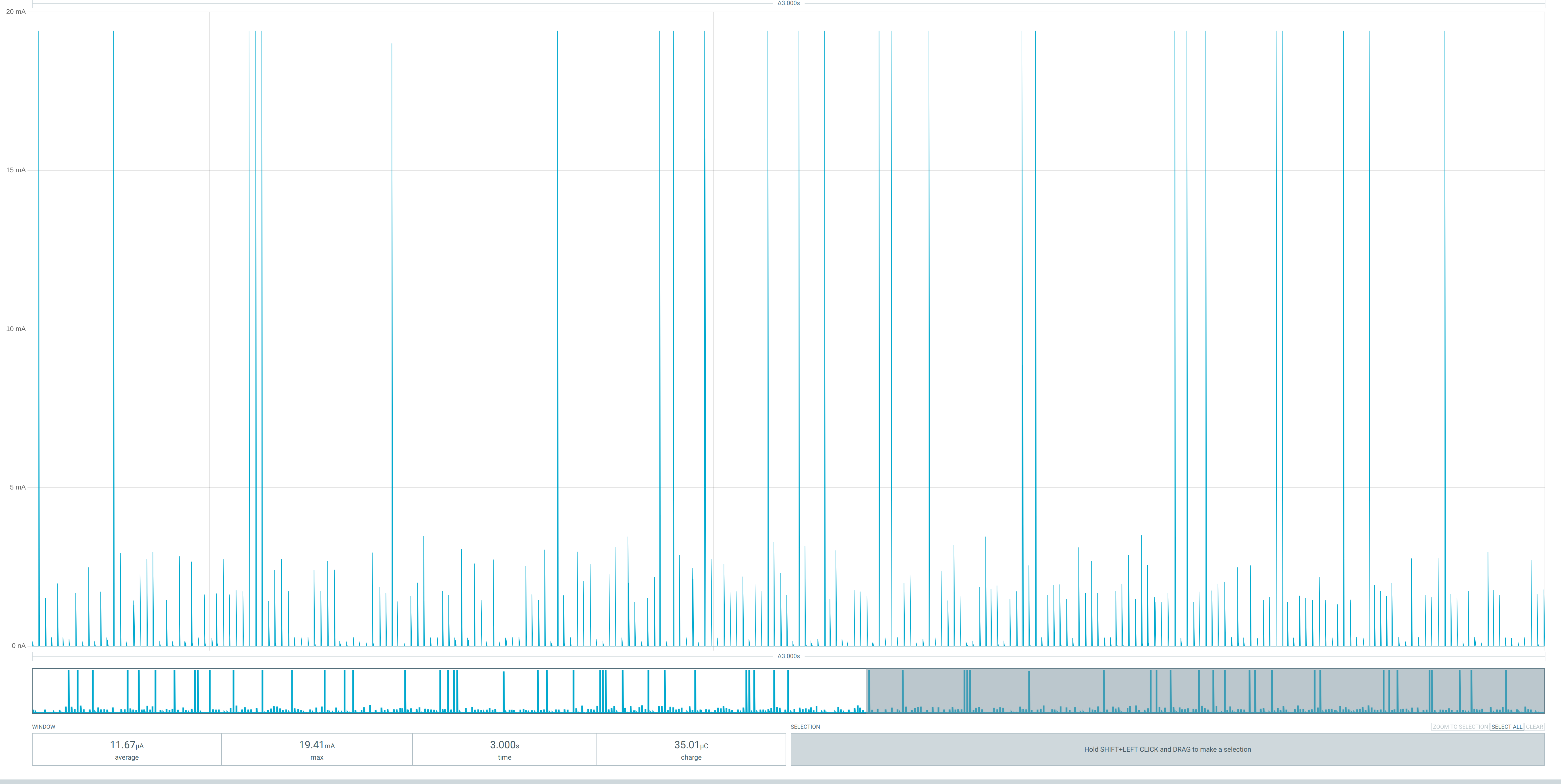
12 microamps average while asleep on the current build. You can see that it is actually very “spiky”. This is because the power regulator itself switches on and off, so it does a large pulse and then coasts for a while, pulse again, and so on.
A very technical post from Jeremy on a communications issue he was debugging a few weeks ago: Debugging hardware is hard – Supermechanical
Any possibility of using an external battery with solar so we can keep the higher data rate? Like a couple of V in pads on the board? That way if you wanted to hack it and add supplemental power (void warranty) it would be a easy hack? I can see using a rechargeable battery and a external MMPT charger and solar panel. Sorry if wrong place to ask this on the forum.
You’ll be able to use an external battery via the USB-C power port. Another backer had a similar question: External battery. Answering there.
Thanks! Good points on the data.
An area I’m working on right now is adding flexibility to how you can display data from Pickup. Here’s a screenshot.
I got more mainboards up and running! Programming/self tests pass on 9 out of the 10 in the batch. The 10th is probably fixable, I just haven’t had time to investigate it yet.
We are pretty happy with the mainboard overall, and are starting what is (hopefully) our final rev, and then set up production for another 50-100 units. Along with that, I am starting work on the production test system that the factory will use to verify they have assembled the board correctly. That’s a subject for another post, but much of it is actually the same electronics that Pickup already uses, but packaged in a different way and running slightly different software. Since it reuses so many components, subcircuit, firmware, and tools, it should be a relatively quick and easy design. More on that as I make progress…
We might also get a smaller test rev in between all of that - PCBs only. The current battery contacts are not satisfactory, so we are going to try and fix that before the next build. Otherwise, we are pretty happy with everything else.
1 Like
Happy Friday everyone!
I’ve been working on the first rev of the manufacturing test system. The basic idea is that you insert a mainboard into a slot in the test system, plug in the cables, and then the system programs the board and checks all of the components and sensors to make sure they were soldered correctly and work.
This is the initial version - just enough to do functional test at the factory. We are planning a slightly fancier version that we will use in house for final testing (so, every mainboard will actually go through two test systems before it ships). The in house testing (which will be done in Austin) covers extra things: measure power consumption of various components and operating modes, calibrate sensors, program shipping firmware, load security certificates, etc.
Here’s the 3D view of the board:
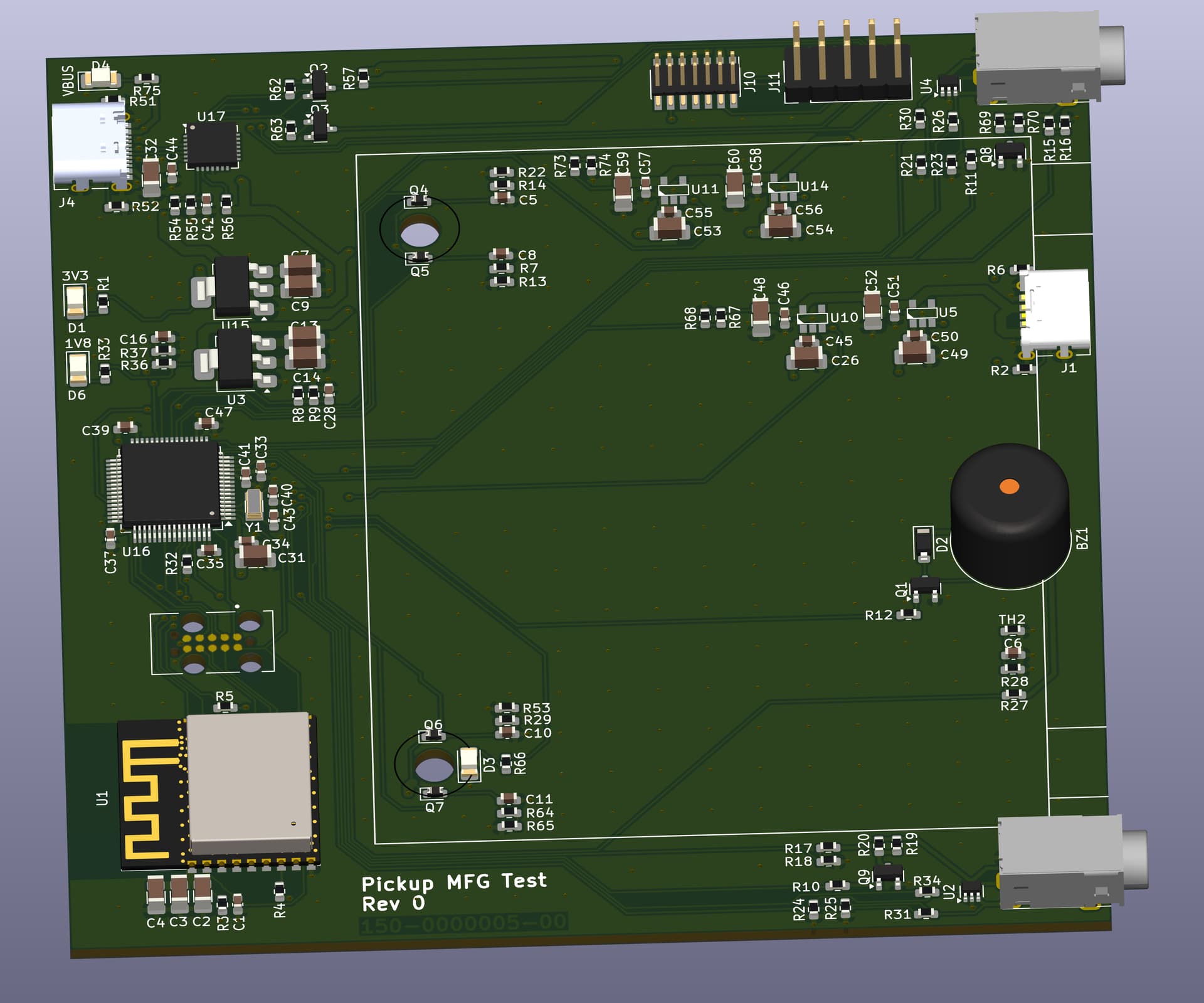
That black cylinder on the right side is a buzzer, to test the microphone. It’s probably going to be pretty annoying for the test operators (which in Austin will likely be me!), but it is necessary to actually test the mic!
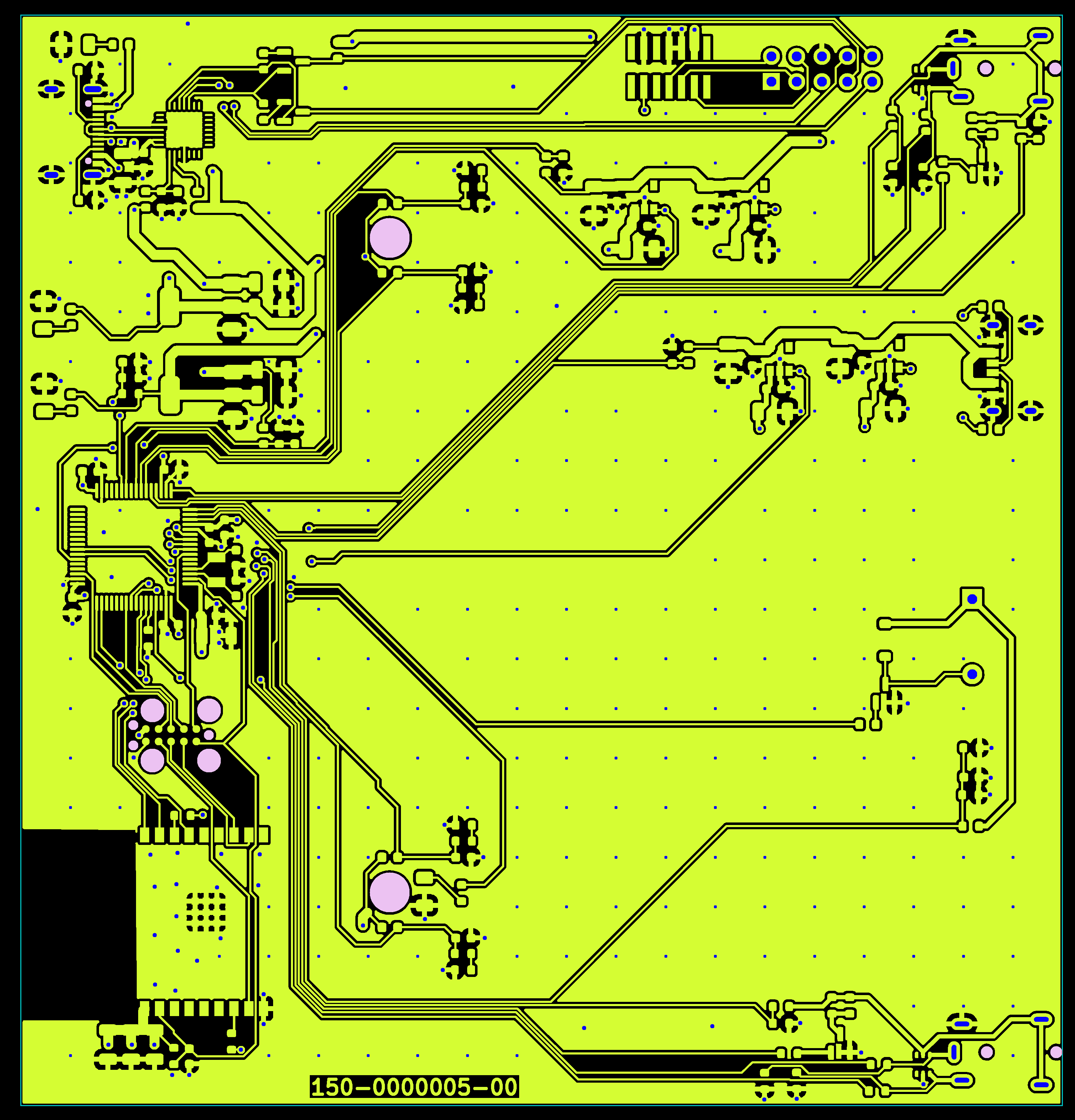
Here’s another view, of the top copper layer of the PCB. This is called a “gerber”. We have one for each layer of the board, and they are used to create the tooling to manufacture the PCB. We review the gerbers layer by layer to make sure the copper and other features are exactly the way we intend them. While most Pickup boards are 2 and 4 copper layers, my record is 14. You can probably guess it takes a while to review that many ![]()
I’ve designed this system to go together in a hurry (I started the project on Monday, and it’s nearly ready for assembly now). 99% of the components are from the Pickup mainboard, in fact, I actually started by copying the mainboard design over and then changing what I needed. This gives us a huge head start: all of the parts are already in our system and we already have working firmware projects for the two microcontrollers. I just need to modify the firmware to operate the test system but all of the low level stuff already works.
We are still working out the battery contact situation, but think we have a path forward. Once we have that resolved and a working test system, we can move forward with the next mainboard build. And then from there, start work on the cartridges and cloud stuff.
Cheers, y’all!
Hello!
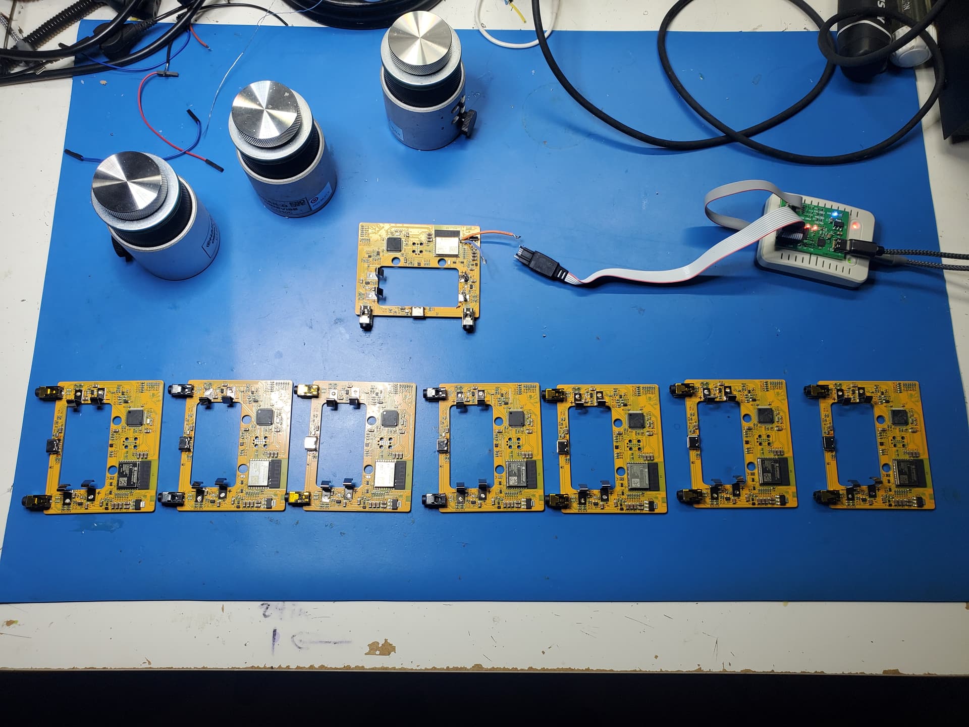
Here’s the MFG test board from last time!
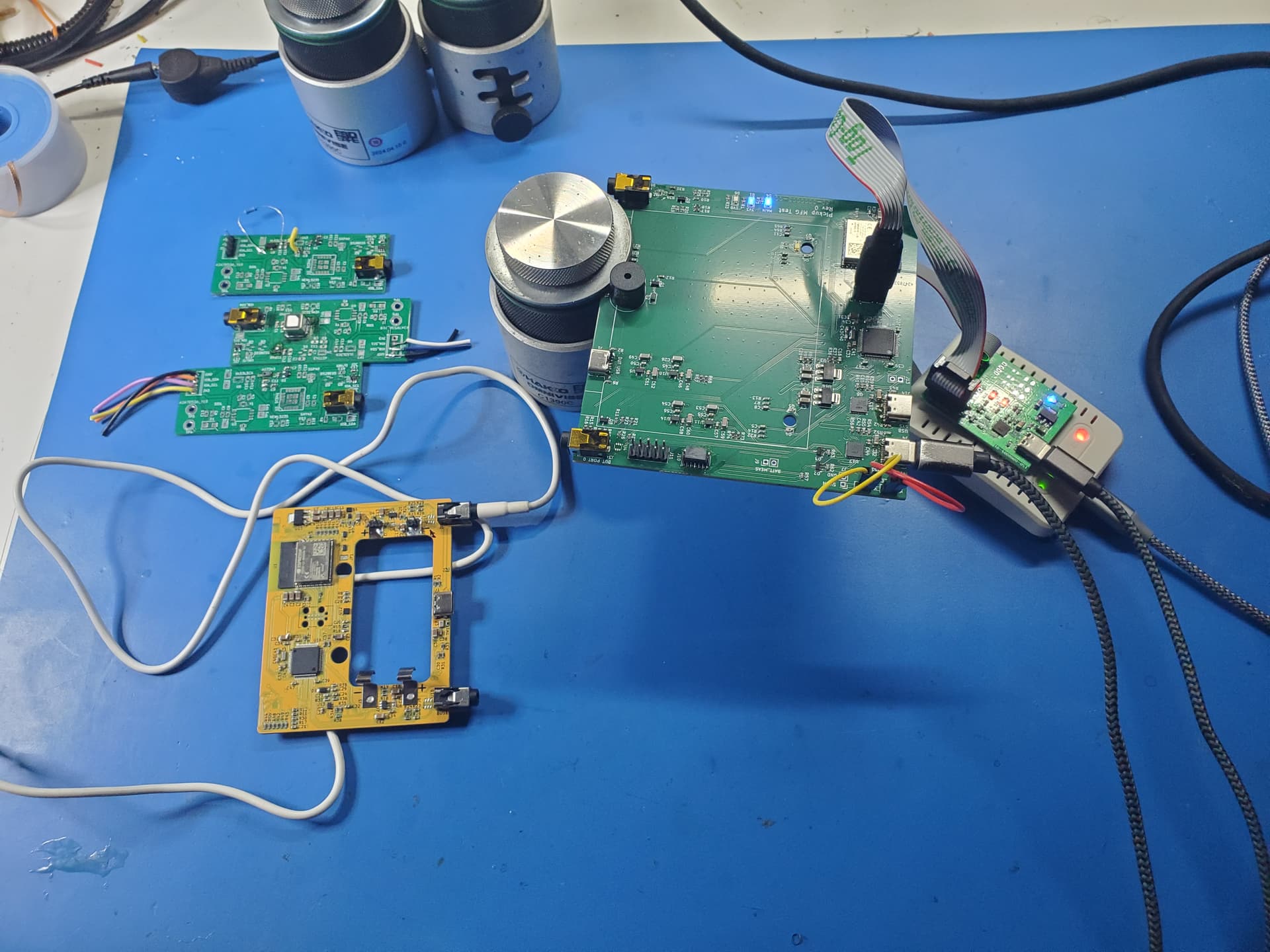
It powers up, the USB ports enumerate, both MCUs program. I need to write the actual test firmware still, but that is considerably simpler than the actual application firmware the devices will ship with.
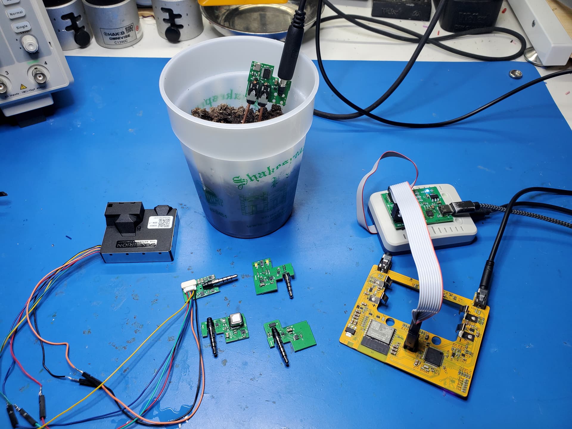
On the left are 3 prototype peripheral boards, covering CO2, VOC, laser ranging, and spectral sensors. All 4 sensors are working and reporting data (when plugged in, of course!), though the spectral sensor needs a bit more work to convert the raw data into something that is more usable. We will do a deeper dive into all of that once we have more software running to actually visualize the data - all I have right now is a raw console.
It is worth noting that all of those sensors are miserable to hand mount on the board. They all have unique packages and requirements, tiny leads that are underneath the part, and tend to melt when heated, which is tricky because that is how soldering works. Some of those took me 1-2 hours to hand mount for a single chip (and on some of them I went through several chips before I got it right). Thankfully, the machines that do this at production have a much easier time of it.
We’ve started discussions with our assembly partner to get the next round of mainboards built. This is going to be an exciting round because the next batch will be boards that will eventually be shipping to you!
Under the hood there has been a lot of firmware progress. Those peripheral boards are detected when plugged in and the appropriate drivers are loaded automatically. I’ve made various improvements to the MQTT infrastructure running on the ESP32, fixed memory leaks and regained some wasted space, improved robustness of a couple things, etc. There’s still a way to go, but the device actually does function pretty well already!
Have a great weekend y’all!
I’ve been mostly working on server stuff lately, which doesn’t lend itself to explanations or visuals. But I’ve also got some pretty multi-channel graphs working. Here’s a screencap of three Pickups reporting light levels (got some noise in two of them caused by LEDs that are blinking for debugging purposes).
1 Like
We have been boring lately! I’m doing a lot of backend work, getting the server processes working efficiently (theoretically a lot of Pickup data to store) and playing well with each other. On the web app side, I’ve been making it more resilient against network outages. Not quite offline-capable yet, but work that will pay off in the long run.
On the production side, I’ve been pushing and pushing the mold maker to get the molds started—they pushed us back in line, apparently because we were making too many changes. (Sorry, I’m trying to get it right and mold makers prefer firm models where they can say “don’t do that”, rather than sketches where they can tell us which path works better, so the iterating is slow.) But I’m told they’re starting next week, which could mean samples by the end of October. I’m trying to get more clarity on the schedule there.
The first PCBs are a little closer. The assembler is making the first 50. I’ll let Jeremy tell you more about that, but here’s a photo.
Hi everyone!
As John said, it’s been a bit “boring” lately. I had some extensive travel, and then also moved to a new house, so I’ve been catching up a bit.
We have 50 mainboards in production, and this will be our test batch before we kick off a run of almost 1000. We’ve already identified some PCB adjustments that need to be made, even before getting them in hand - just tweaks to make them easier to mass produce so far.
Other than that, we’ve been working on backend stuff. John got a lot of server/database stuff up and running, and now I’m making final design changes to our MQTT firmware to support that.
We are actually approaching an inflection point. The mainboard design is pretty stable and we will be verifying our test processes with this batch. Now with the prototype server running, we can start on some of the final module design and use our own system to collect data and verify everything is working the way it should.
We should have more interesting updates in the coming weeks.
Cheers!
-J
Happy Friday!
I’ve been working on a lot of firmware features. We have the core of our system configuration working. Lots of basic things like enabling sensor channels, setting if you want them to record to the database, and per-channel sampling rates. Oh, and firmware updates over MQTT!
Also, I finally got around to testing all of our mainboards from our batch of 50:
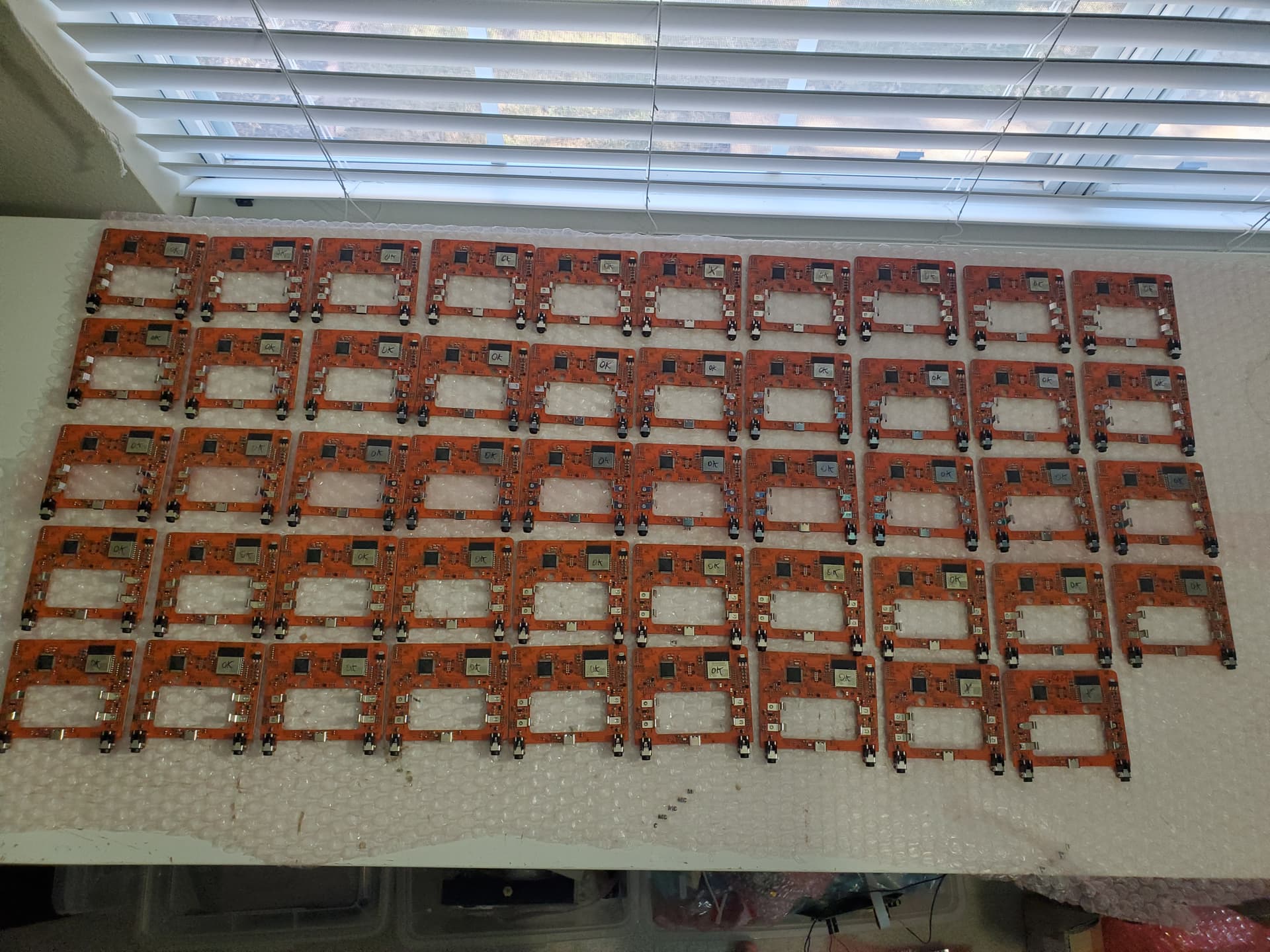
That’s 49 boards. John has the last one. I’ve tested them on a basic hardware test. 47 of 50 pass with no issues! Not bad. If you look closely you’ll see a few have an X instead of OK. The issues I found:
- One board has a bad LED connection. Easily fixed with a hot air station.
- One board is throwing some very odd initialization errors with the random number generator. I think the hardware is actually fine on this one and this is some bug in ST’s init code for the RNG, but I’ve marked it as a fail for now and will investigate it more thoroughly next week.
- One board is not establishing the link between the two microcontrollers. This is probably a solder joint issue, as both MCUs program individually.
All in all, not bad for our first true production batch, and other than the RNG, probably simple fixes. It is normal to have a few issues to be fixed with some quick soldering rework (this is why we test test test!).
This is all done on a fairly basic test system we will be sending to our supplier in China. We are going to have a more thorough test system that we run in Austin (I have the hardware and basic firmware support, but haven’t had time to write the test software yet), that will be a lot more thorough and will characterize various parts of the board, measure power consumption, and check a few more things that our basic test can’t get to.
Cheers!
Jeremy
Wow, last update was October? I’ll try to do better!
As always, ping us if you haven’t heard from us in a while!
So what’s new?
Production modules!
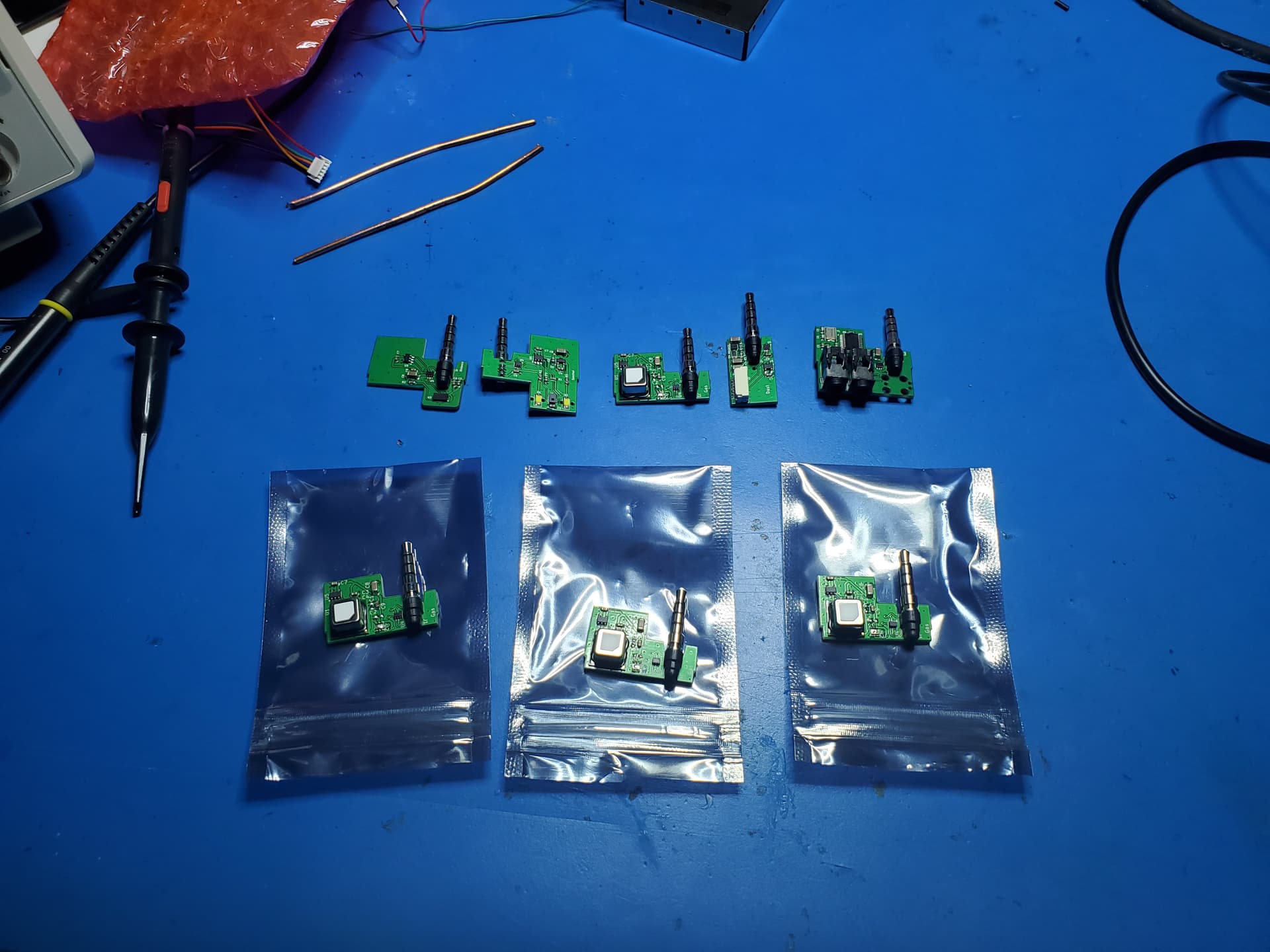
We received 4 samples each of 5 of our bespoke sensor cartridges and they all work!
There’s still a fair amount of work to be done on the firmware side, but the hardware works and we have raw feeds of the sensors. Some of them are pretty usable as-is, some need some tweaking (the spectral sensor being a major one, the raw output is not terribly usable - but we will be refining that).
I’ve also gotten a lot more firmware infrastructure running. A lot of it has been very boring but extremely important stuff like configuration data structures and the mechanisms to load and store configs on the device.
One of the things we’ve really focused on through this entire process is how to narrow down the feature set and capability to just what we really need for the user experience we want. There is a balance between power/flexibility and simplicity, and there have been multiple times when we realized we were implementing something very powerful but also very complicated. If it is too complicated, no one is going to use it, and it also makes our work more difficult and time consuming.
Configuration is one of those. I had a (pretty neat, to be fair!) custom syntax that could do some really powerful things, but it was only going to be useful if you had 100+ devices to configure, and was frankly a bit overwhelming if you had 1 or 2. No one bought 100 devices from us, so I was solving a problem we frankly didn’t actually have, and creating a lot more work for us both in the process.
Now, I have a system that is much simpler and uses fairly standard tools and techniques. For the techies/programmers out there, the config data is now done with a human readable JSON data structure. For the less technically inclined, JSON is basically a data format that is widely used across the entire software industry and is renowned for being easy to use both for humans and machines.
The config for one of my test devices looks like this:
"pickup_583250090035005c": {
	"name": "jeremys_pickup",
	"device": {
		"telemetry_rate": 20.0,
		"sensor_rate": 1.0,
		"mode": "fast"
	},
	"wifi": {
		"ssid": "********",
		"pass": "********"
	},
	"cloud": {
		"enable": true,
		"url": "mqtt://saturn2.local:1883"
	},
	"modules": {
		"internal": {
			"monitor": true,
			"record": true,
			"sensor_rate": 2.0
		},
		"co2": {
			"monitor": true,
			"record": true,
			"sensor_rate": 10.0
		}
	}
}
Even if you don’t speak computer, you can probably guess what a lot of that does.
Most of that isn’t stuff you’ll ever need to interact with directly (though part of our reasoning is that we do want it to be easy/approachable for users to create their own tools if they are so inclined). Our app will do most of the low level config for you. But it definitely makes our work easier, and allows us to focus more on other things you’ll actually care more about.
That configuration data touches almost every part of our system in some way, so it was critical to get it right. I think we’ve got it, and it’s enabled us to move forward on a lot of other things, like the aforementioned modules that we now have samples of. We need to be able to configure the modules in a flexible but simple way since you can swap out modules and have different settings for each type.
While doing all of this work with the modules, I also finally tracked down a glitch I’d been seeing. Basically, when you plug/unplug a module, there is a chance of the electrical contacts in the connector briefly short circuiting the power supply in Pickup. Sometimes this does nothing, but sometimes it is enough of a glitch that the WiFi processor restarts. You can’t damage anything this way (the hardware is designed to handle faults like that), but it does need to be gracefully handled in software so the system keeps running without you needing to do anything about it.
Here’s what this looks like:
The yellow trace is the main 3.3V power supply that runs most of the electronics.
The pink trace is the module power supply. It runs at 3.3V but has a power switch circuit that also acts as a circuit breaker.
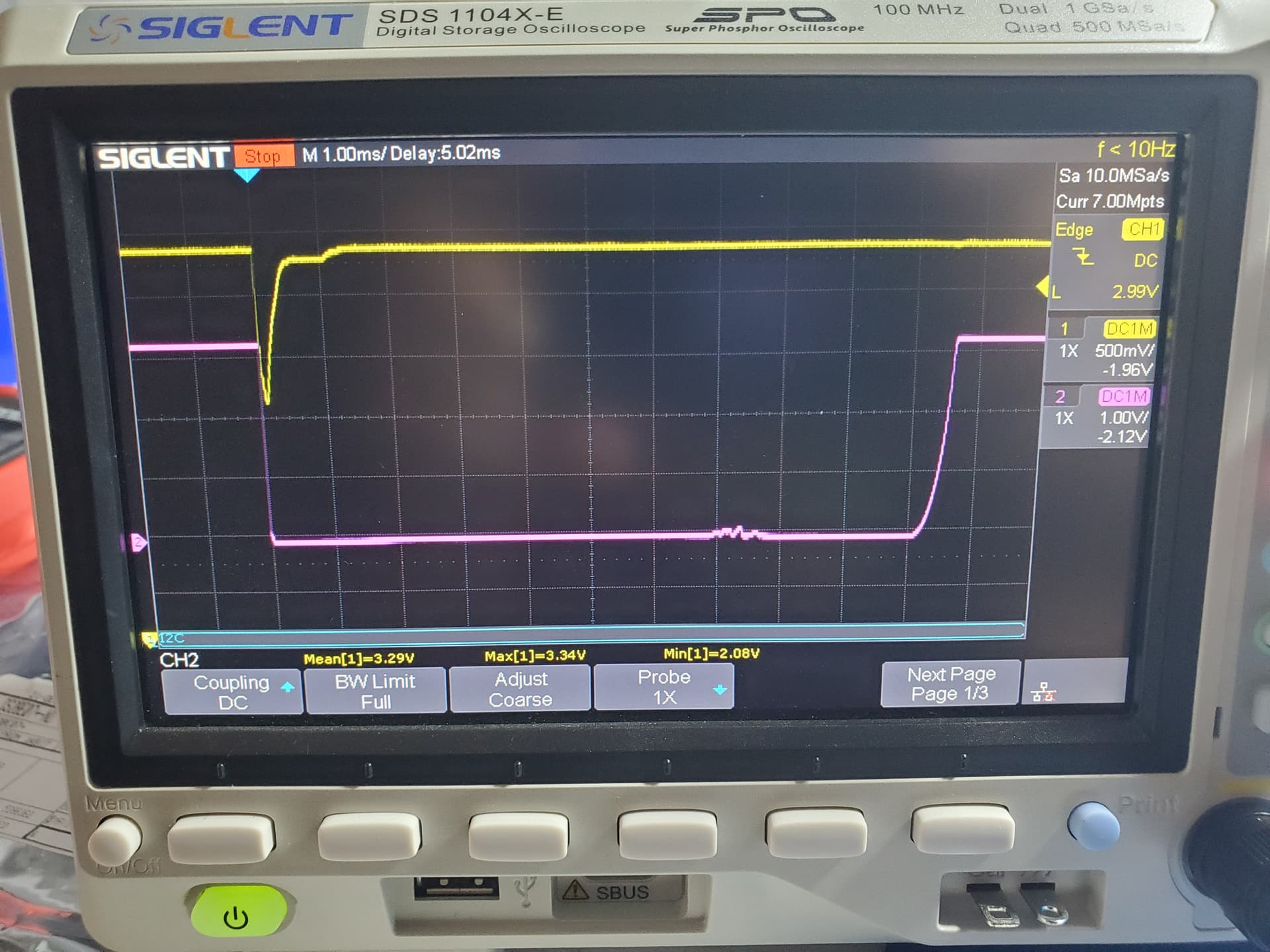
There’s a brief glitch on the 3.3V (yellow), about half of a millisecond (1/1000 of a second - which for electronics is an eternity). The WiFi processor will typically cut out with a glitch like that.
In the pink, that is the module power being turned off by the hardware power controller. It sees a short circuit and turns off for a while to protect everything from damage, and then turns the power back on.
Before last week, Pickup would just hang up at this point, since of one of the CPUs stops and the other one didn’t know what to do. Now we can detect this and we just gracefully restart the WiFi if needed. I’ve got a few more firmware tricks up my sleeve to improve that behavior even further, but it is a lower priority so I can focus on some other things for near future.
OK that’s about all for now. I will try to do better than 4 months between updates! As always, ping us if you’d like to hear from us! We have been very busy - there’s a lot that goes in to a product like this, and the time kind of flies past.